Safety Investigation Report 2018:1 Factual Information/1.9
SAFETY INVESTIGATION REPORT MH370 (9M-MRO)
1.9.1 High Frequency System
This aircraft was installed with Collins HFS-900 High Frequency (HF) System. The HF communication system on this aircraft uses two HF systems with a common HF antenna to transmit and receive radio frequency (RF) signals in the HF range.
The HF transceiver operates within the frequency range of 2,000 MHz to 29,999 MHz and one KHz channel spacing.
The Left Transfer bus sends 115V AC three-phase power to the Left HF communication system. The Left HF communication transceiver supplies 115V AC single phase to the Left HF antenna coupler for operational power. It also supplies 28V DC for the key interlock function. The Right HF communication system is the same as the Left, except that it uses power from the Right AC Sec 2 bus.
1.9.2 Very High Frequency System
This aircraft was installed with Collins VHF-900B VHF System. The very high frequency (VHF) communication system permits voice and data communication over line-of-sight distances. It permits communication between aircraft or between ground stations and aircraft. The VHF system operates in the VHF aeronautical frequency range of 118.000 MHz to 136.992 MHz.
The VHF communication system on this aircraft uses three VHF systems. Each VHF system has a VHF antenna and a VHF communication transceiver.
The VHF communication system connects with Selective Calling Equipment (SELCAL) decoder that starts an alert when a call comes in for that aircraft.
The captain’s flight instrument bus sends 28V DC to the Left VHF communication transceiver and the Left Radio Tuning Panel (RTP). The Left Main DC bus sends 28V DC to the centre VHF communication transceiver and the centre RTP.
The Right Main DC bus sends 28V DC to the right VHF communication transceiver and the right RTP.
1.9.3 Air Traffic Control/Mode S Transponder System
This aircraft was installed with a Bendix/King TRA-67A Mode S transponder. The Air Traffic Control (ATC) ground stations interrogate the airborne ATC/Mode S transponder system as shown in Figure 1.9A (below).
The ATC/Mode S transponder replies to the interrogations in the form of coded information that the ground station uses. The ground station uses a Primary Surveillance Radar (PSR) to get radar returns from aircraft within the radar range. To make a communication link with the aircraft in the radar range, the ground station uses a Secondary Surveillance Radar (SSR) to interrogate the ATC/Mode S transponder. The ground station transmits a side lobe suppression signal to inhibit close ATC replies that come from a SSR side lobe transmission.
Figure 1.9A - Air Traffic Control/Mode S Transponder System
Copyright © Boeing. Reprinted with permission of The Boeing Company
On the ground radar display, the Air Traffic Controller (ATC) sees the radar returns, altitude, and a four digit aircraft identifier. The ATC also sees aircraft derived Enhanced Surveillance downlink data on the ground station radar display, such as Magnetic Heading, Air Speed (Indicated Air Speed and Mach number), Ground Speed, Roll Angle, Selected Altitude, True Track Angle, andVertical Rate.
The ATC/Mode S transponder also replies to mode S interrogations from the Traffic Alert and Collision Avoidance Systems (TCAS) of other aircraft. ATC/Mode S transponders with Extended Squitter function provide broadcast of Global Position System (GPS) position and velocity data.
Two transponders are installed on the aircraft. A Transponder selector switch on the Transponder panel in the cockpit allows selection of either the left or the right transponder. During normal operations the crew procedure is to leave the left transponder selected on the panel. There is no automatic switching between the transponders if one fails. It must be done manually by the pilots. Failure of either of the transponders will be annunciated in the cockpit. The Left ATC/Mode S transponder gets 115V AC power from the AC Standby bus. The Right ATC/Mode S transponder gets 115V AC power from the Right AC Transfer bus. Thedual transponder panel gets 115V AC power from the AC Standby bus. The two transponders are powered by highly reconfigurable AC buses; the left one can be powered by the battery if the left AC bus is unavailable (the AC Standby bus can be powered by the left Transfer bus or the battery), and the AC Transfer busses also have their alternate sources.
This system can be deactivated (turned OFF) by pulling the circuit breakers located at the P11 overhead circuit breaker panel or by selecting the Transponder Mode Selector (Transponder Panel) to “STBY” position. The transponder on the occurrence flight was operating satisfactorily up to the time it was lost on the ATC radar screen at 1721.13 UTC, 07 March 2014 [0121:13 MYT, 08 March 2014]. There was no message received from the aircraft to report a system failure.
Sub-page List
- 1 Factual Information/1.9/1.9.1 HF
- 1 Factual Information/1.9/1.9.2 VHF
- 1 Factual Information/1.9/1.9.3 Mode S Transponder
- 1 Factual Information/1.9/1.9.4 ACARS
- 1 Factual Information/1.9/1.9.4 ACARS/1
- 1 Factual Information/1.9/1.9.4 ACARS/1/APU Report
- 1 Factual Information/1.9/1.9.4 ACARS/1/Link Established
- 1 Factual Information/1.9/1.9.4 ACARS/1/Loadsheet
- 1 Factual Information/1.9/1.9.4 ACARS/1/NOTOC
- 1 Factual Information/1.9/1.9.4 ACARS/1/Position Report
- 1 Factual Information/1.9/1.9.4 ACARS/1/Printer
- 1 Factual Information/1.9/1.9.4 ACARS/1/Take-off and Climb
- 1 Factual Information/1.9/1.9.4 ACARS/Intro
- 1 Factual Information/1.9/1.9.5 Satcom
- 1 Factual Information/1.9/1.9.5 Satcom/1
- 1 Factual Information/1.9/1.9.5 Satcom/2
- 1 Factual Information/1.9/1.9.5 Satcom/3
- 1 Factual Information/1.9/1.9.5 Satcom/4
- 1 Factual Information/1.9/1.9.5 Satcom/5
1.9.4 Aircraft Communications Addressing and Reporting System
The Aircraft Communications Addressing and Reporting System (ACARS) is a digital data-link system that manages flight plan and maintenance data between the aircraft and the Ground Service Provider (GSP) by using radio i.e. VHF or satellite communications (SATCOM) as shown in Figure 1.9B (below).
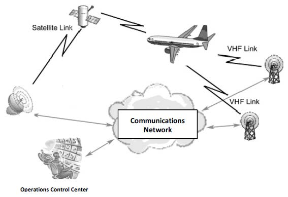
Figure 1.9B - ACARS System
Source:
Safety Investigation Report MH370/01/2018
ACARS provides message communication between aircraft and its base (ground). The following messages are transmitted:
- Out of the gate, Off the ground, On the ground, and Into the gate (OOOI) events:
- Out of the gate event: Departure from the gate with all doors closed and parking brake released;
- Off the ground event: Take-off with the nose gear squat switch extended;
- On the ground event: Touch down with the nose gear squat switch compressed; and
- Into the gate event: Parked at the gate with the parking brake set and the door open.
- Flight plans: ACARS interfaces with Flight Management Systems (FMS) acting as the communication system for flight plans to be sent from the ground to the FMS. This enables the aircraft to update the FMS while in flight and allows the flight crew to evaluate the alternative flight plans including the status of connecting flights.
- Weather information: ACARS interfaces with FMS, acting as the communication system for weather information to be sent from the ground to the FMS. This enables the aircraft to update the FMS while in flight and allows the flight crew to evaluate new weather conditions.
- Equipment health: ACARS is used to send information from the aircraft to ground stations about the conditions of various aircraft systems and sensors in real-time. Maintenance faults and abnormal events are also transmitted to ground stations along with detailed messages, which are used by MAS for monitoring equipment health, and to better plan the repair and maintenance activities.
- Aircraft positions which provide latitude and longitude, altitude, speed, total air temperature, total remaining fuel, wind direction and speed and heading.
- Engine performance data which provide engine data during take-off, climb, cruise and approach.
ACARS interfaces with the Multifunction Display (MFD) in the cockpit, which flight crew can use to send and receive technical messages and reports to or from ground stations, such as a request for weather information or clearances or the status of connecting flights. The response from the ground station is received on the aircraft via ACARS as well. The ACARS Manager page in the Communications main menu on the selected Multifunction Display (MFD) is used for this purpose. The COMM display switch, located on the display select panel, displays the communications main menu on the selected MFD. The ACARS Manager page allows the flight crew to independently select/deselect VHF or SATCOM transmission of data.
The ACARS communicates through either the VHF or the SATCOM systems. The ACARS datalink connects to the Satellite Data Unit (SDU) of the SATCOM system and the Center and Right VHF Communication Transceivers of the VHF systems. The Center VHF exchanges data with the ACARS modem in the Communications Core Processor Module (CPM/Comm) of the Left AIMS cabinet. The right VHF exchanges data with the ACARS modem in the CPM/Comm of the Right AIMS cabinet. The ACARS does not interface with the Left VHF Transceiver.
For the ACARS operation the Data Communication Management Function (DCMF) of the AIMS uses the voice/data select to set the VHF Communication Transceiver to the data signal mode. At power-up, the DCMF sets the Center VHF Communication Transceiver to the data signal mode. If the Center VHF Communication Transceiver fails, or voice is selected manually by the flight crew, the DCMF selects SATCOM for data transmissions. If SATCOM fails, the DCMF selects the Right VHF Communication Transceiver for data transmissions. The Left VHF Communication Transceiver is voice only. On the event flight, as instructed by Ground Operations via text message shown on the MFD (shown as ‘Switch VHF3 to Voice’), the flight crew would have selected voice on the Center VHF resulting in SATCOM being used for the data transmissions. Refer to page 1 of Appendix 1.9A – ACARS Traffic Log. The use of SATCOM for the ACARS transmissions is evident in the SATCOM Ground Station Logs [refer to Section 1.9.5, para. 4)]. This switching from VHF to SATCOM for the data transmissions is normal practice in MAS for commercial reasons.
In the event that the aircraft ACARS unit has been silent for longer than a pre-set time interval, the ground station can ping the aircraft (directly or via satellite). A ping response indicates a healthy ACARS communication. This ping is different from the Satellite ping or handshake.
Pre-set time interval for MAS B777 is 30 minutes. When the aircraft ACARS is silent for more than 30 minutes, MAS Operation Control Centre (OCC) is required to send a text message via ACARS to the cockpit or to call the cockpit via SATCOM.
1) Aircraft Communications Addressing & Reporting System Traffic Log
ACARS traffic log messages sent/received to/from 9M-MRO between 1554:41 UTC, 07 March 2014 [2354:41 MYT, 07 March 2014] until 1815:25 UTC, 07 March 2014 [0215:25 MYT, 08 March 2014] is shown in Appendix 1.9A. Some key events are extracted and explained below.
At 1554:41 UTC, 07 March 2014, ACARS data link was fully established on SATCOM transmission and at 1556:08 UTC the flight information (FI) MH0370 and Aircraft Number (AN) 9M-MRO were keyed in by the crew as per Figure 1.9C (below).
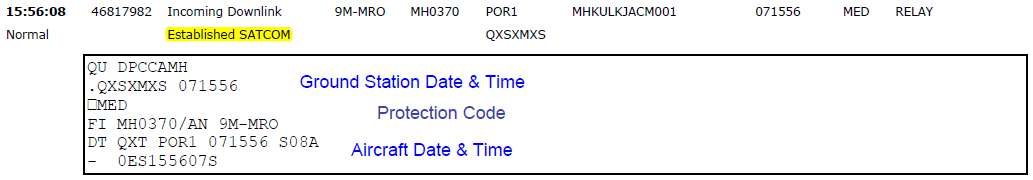
Figure 1.9C - ACARS data link established SATCOM transmission
Source:
Safety Investigation Report MH370/01/2018
Notice to Crew (NOTOC) was sent at 1606:15 UTC on 07 March 2014 [0006:15 MYT, 08 March 2014] direct to the aircraft printer and to be printed out by the crew.
NOTOC from the ground station to the cockpit stated the special loads of total 4,566 kg of mangosteens were carried on board. Details of the mangosteens were:
- 1,128 kg at station 41L,
- 1,152 kg at station 41R,
- 1,148 kg at station 43L, and
- 1,138 kg at 44L respectively.
(Refer to Section 1.18.2 for details of cargo carried).
Declaration of “there is no evidence that any damaged or leaking packages containing dangerous goods have been loaded on the aircraft at this station” was also written in the NOTOC message. Figure 1.9D (below) shows the snapshot of the ACARS NOTOC message.
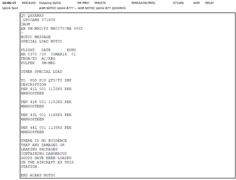
Figure 1.9D - Snapshot of ACARS NOTOC message
Source:
Safety Investigation Report MH370/01/2018
Aircraft final loadsheet was sent via ACARS at 1606:32 UTC, 07 March 2014 [0006:32 MYT, 08 March 2014] direct to the aircraft printer and to be printed out by the crew. Details of aircraft weight as stated in the final loadsheet are discussed in Section 1.6.5.
Figure 1.9E (below) shows the snapshot of the final loadsheet of this aircraft.
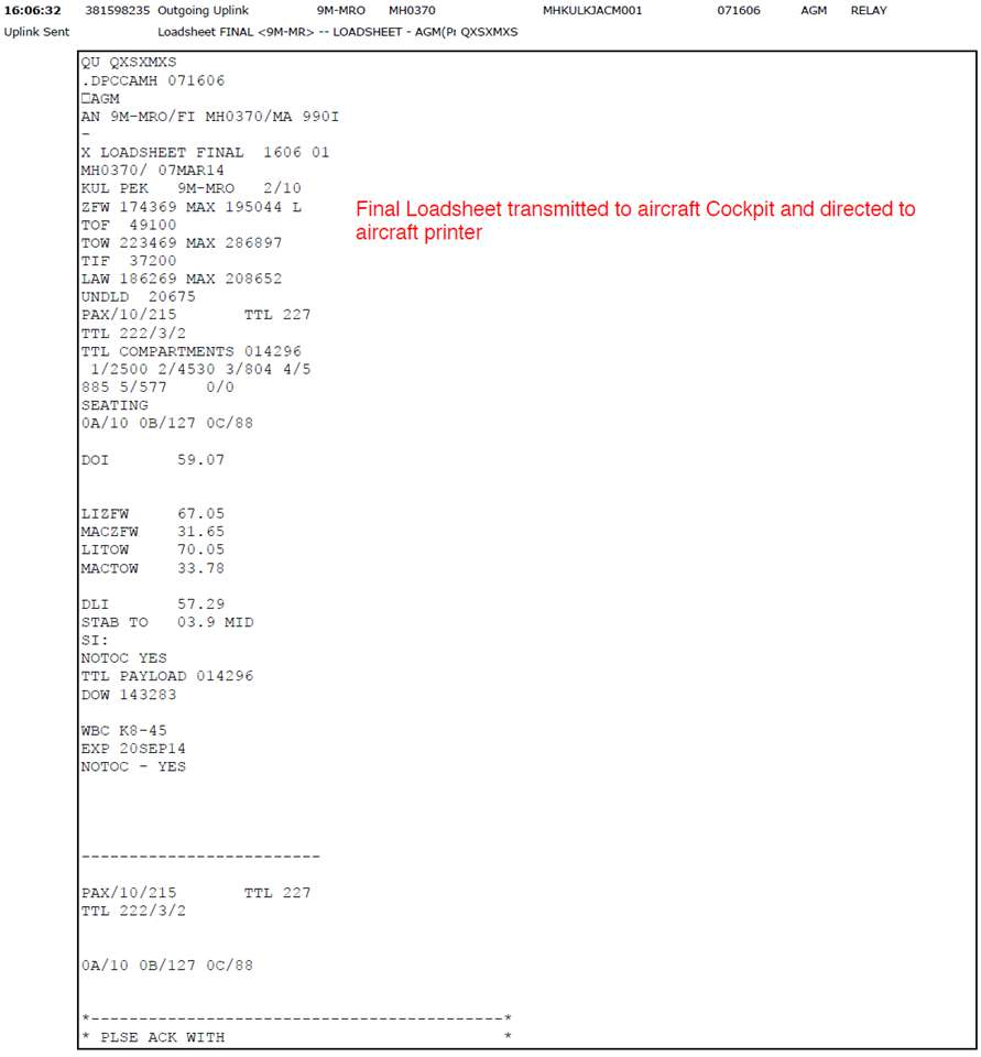
Figure 1.9E - Final Loadsheet
Source:
Safety Investigation Report MH370/01/2018
Pilot acknowledgement and confirmation of the final loadsheet is shown in the ACARS snapshot in Figure 1.9F (below).
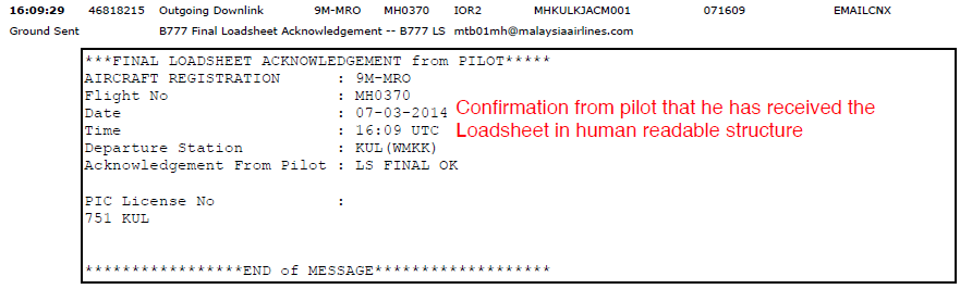
Figure 1.9F - Final Loadsheet Acknowledgement
Source:
Safety Investigation Report MH370/01/2018
Data on aircraft APU is shown in Figure 1.9G (below). APU report generated by ACMS sent via ACARS at 1629:33 UTC stated the total APU cycles and hours were 15,699 cycles and 22,093 hours. APU hours for the previous flight was 4 hours.
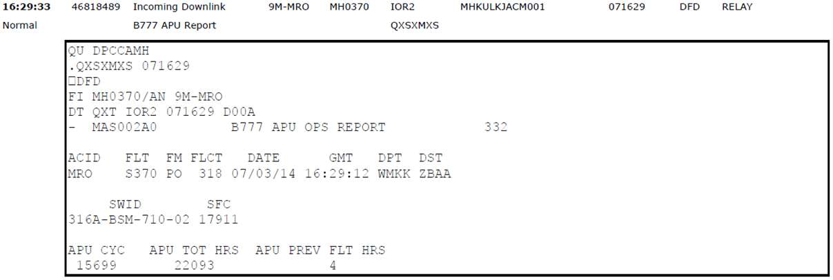
Figure 1.9G - APU Report
Source:
Safety Investigation Report MH370/01/2018
Engine take-off and climb reports transmitted via ACARS are explained in Section 1.6.4 para. 8). Engine parameter reports were transmitted to MAS and then to Rolls Royce for Engine Health Monitoring (EHM). Appendix 1.9A shows these data in coded form. The decoded data are shown in Appendix 1.6B.
The first (which was also the last) position report was transmitted via ACARS at 1707:29 UTC, 07 March 2014 [0107:29 MYT, 08 March 2014]. This was a collation of 6 reports generated at 5-minute intervals by the system at 1641:43 UTC, 1646:43 UTC, 1651:43 UTC, 1656:43 UTC, 1701:43 UTC and 1706:43 UTC, 07 March 2014. Parameters transmitted are as per Table 1.9A (below). The actual traffic log on the position report is reproduced in Figure 1.9H (below). Position reports were programmed to be transmitted every 30 minutes.
Note: Aircraft position information is also included in the EHM take-off and climb reports.
| Greenwich Mean Time (GMT) - UTC | 1641:43 | 1646:43 | 1651:43 | 1656:43 | 1701:43 | 1706:43 |
| Altitude (ALT) – Feet | 103 | 10,582 | 21,193 | 28,938 | 34,998 | 35,004 |
| Calibrated Airspeed (CAS) - Knots | 168.4 | 261.8 | 301.1 | 303.1 | 278.0 | 278.4 |
| MACH | 0.255 | 0.478 | 0.669 | 0.783 | 0.819 | 0.821 |
| Total Air Temperature (TAT) - °C | 31.1 | 23.4 | 11.6 | 2.6 | -13.4 | -13.1 |
| Static Air Temperature (SAT) - °C | 27.3 | 10.4 | -11.8 | -27.4 | -43.9 | -43.8 |
| Latitude (LAT) | 2.767 | 3.074 | 3.553 | 4.109 | 4.708 | 5.299 |
| Longitude (LONG) | 101.715 | 101.760 | 101.988 | 102.251 | 102.534 | 102.813 |
| Gross Weight (GWT) – lb | 492,520 | 489,200 | 486,240 | 483,840 | 481,880 | 480,600 |
| Total Remaining Fuel Weight (TOTFW) - kg | 49,200 | 47,800 | 46,500 | 45,400 | 44,500 | 43,800 |
| Wind Direction (WINDIR) | 140.3 | 107.6 | 91.8 | 58.4 | 69.6 | 70.0 |
| Wind Speed (WINDSP) | 1.25 | 9.38 | 19.50 | 10.63 | 17.38 | 17.13 |
| True Heading (THDG) | -33.5 | 27.3 | 27.8 | 26.0 | 26.8 | 26.7 |
| Note: Values in bold have been corrected using data from the original ACARS position report. | ||||||
Table 1.9A - ACARS Position Report
Source:
Safety Investigation Report MH370/01/2018
1.9 Communications
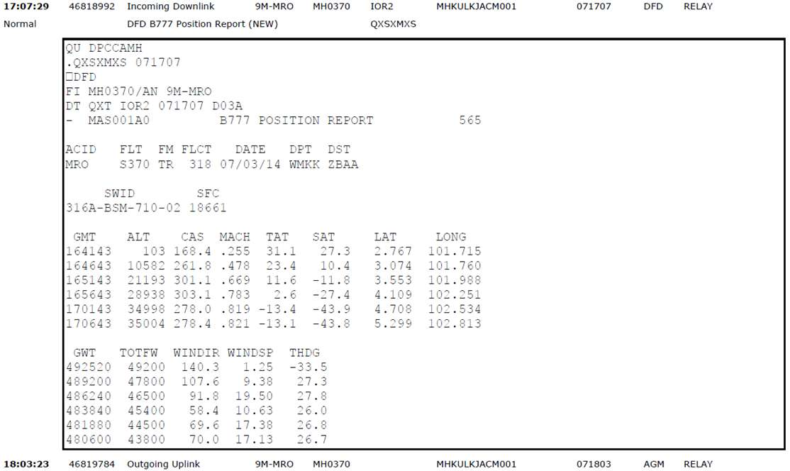
Figure 1.9H - Position Report
Source:
Safety Investigation Report MH370/01/2018
The first message sent to the aircraft cockpit printer from the MAS ODC was at 1803:23 UTC. The ACARS message requested the crew to contact the HCM ACC immediately. The incoming downlink message at 1803:24 UTC showed the message failed to reach the aircraft. Messages are auto transmitted every 2 minutes and the message was retransmitted until 1843:33 UTC but all messages failed to get a response. Automated downlink message by ACARS showed ‘failed’. Message sent to the aircraft cockpit printer and the Automated Downlink messages are shown in Figures 1.9I and 1.9J (below), respectively.
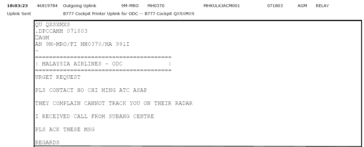
Figure 1.9I - Message from MH ODC
Source:
Safety Investigation Report MH370/01/2018

Figure 1.9J - Automated Downlink Message
Source:
Safety Investigation Report MH370/01/2018
1.9.5 Satellite Communications
1) Satellite Communications System Description
Satellite Communications (SATCOM) is an acronym of, and generic term for, satellite communications. SATCOM operates by using satellites to relay radio signals between the sender and receiver. It can cover far more distance and wider areas than other radios. SATCOM can be used to transmit words, pictures and other forms of information.
The aircraft, 9M-MRO, was equipped with a SATCOM terminal that used the Inmarsat Classic Aero system. The Inmarsat system utilises a constellation of satellites to provide nearly global coverage, the exception being polar areas. The aircraft SATCOM system, also referred to as an Airborne Earth Station (AES) operates on L Band, transmits at 1.6 GHz and receives at 1.5 GHz. For this aircraft, the SATCOM system provided a total of five voice channels and one data channel. The satellite link provides the following functions:
The Earth or Ground Station uses C Band, transmits at 6 GHz and receives at 4 GHz. Inmarsat uses a network of Ground Earth Stations (GES) to communicate with the satellites and connect the SATCOM signal to other terrestrial data networks such as telephone systems, internet, etc.
When the SATCOM AES is first powered on, it sends a log-on request to the GES to initiate service.
There are a number of channels available for messages to be sent between the Satellite and Earth Station. One of the channels is called the ‘common access channel’, which aircraft will constantly listen to when able to do so.
If the GES has not heard from an aircraft for an hour after the last communication, it automatically transmits a ‘log on interrogation’ (“ping”) message on the common access frequency using the aircraft’s unique identifier. If the aircraft receives its ‘unique identifier’, it returns a short message that it is still logged onto the network. Both the initial log-on request and the hourly ping have been termed as a ‘handshake'.
The SATCOM AES consists of the following equipment: Radio frequency unit (RFU), Radio frequency attenuator (RF ATTN), Radio frequency splitter (RFS), Class C high power amplifier (HPA), Class A high power amplifier (HPA), High power relay (HPR), three low noise amplifier/diplexers (LNA/DIPs), Low gain antenna (LGA), two beam steering units (BSUs), two high gain antennas (HGAs), Radio frequency combiner (RFC) and Satellite data unit (SDU).
The SATCOM avionics are located on the E11 rack, which is in the crown area aft of doors 3 left/right. The High Gain antennas are mounted above door 3 left and door 3 right. The Low Gain antenna is mounted on the fuselage centreline. The SATCOM Circuit Breakers (CB) are located in the Main Equipment Center (MEC).
The Satellite Data Unit (SDU) receives 115V AC from the Left Main bus. In flight, this bus can be powered by engine mounted generators or the APU generator. Neither the aircraft battery nor the ram air turbine will power the SATCOM system.
The diagram in Figure 1.9K (below) shows the complete set of SATCOM units, including avionics, High Gain Antenna Subsystem and Low Gain Antenna Subsystem. It also shows interfaces to the aircraft cockpit and cabin systems and functions. The following notes are intended to be read in conjunction with Figure 1.9K (below):
- a) CDU (3) are the three Control Display Units, otherwise known as Multi-function Control Display Units (MCDUs).
- b) CPMU is Cabin Passenger Management Unit, which provides an interface between the Panasonic IFE and the SDU, for any Data-3 SMS/e-mail messages.
- c) AMU is the Audio Management Unit, which feeds cockpit audio to and from the SDU.
- d) CTU is the Cabin Telecommunications Unit, which provides an interface between the in-seat handsets and the SDU, for cabin telephony calls, were that functions available. In the case of 9M-MRO, the in-seat phones can only be used for seat-to-seat calling.
- e) AIMS Cabinet is one of two Airplane Information Management System cabinets, which route numerous information to and from the SDU, including ACARS data, Navigational data, AES ID and Flight ID.
- f) SATCOM Maintenance Switch is not relevant to this document, as no maintenance activity is possible in flight.
Figure 1.9K - SATCOM System
The photo in Figure 1.9L (below) shows the Honeywell/Racal (Honeywell/Thales) MCS-6000 SATCOM Units - RFU (left), SDU (centre) and HPA (right).
2) Satellite Communications Ground Station Logs of the Event - Introduction
Throughout the flight of MH370, the aircraft communicated through the Inmarsat Indian Ocean Region (IOR) I-3 Satellite and the GES in Perth, Australia.
Figure 1.9M (below) shows the Inmarsat I-3 IOR Satellite Coverage Map. The blue lines represent the elevation angle to the IOR satellite for a SATCOM unit on the ground or in the air. Due to the satellite inclination, the elevation angles are approximate.
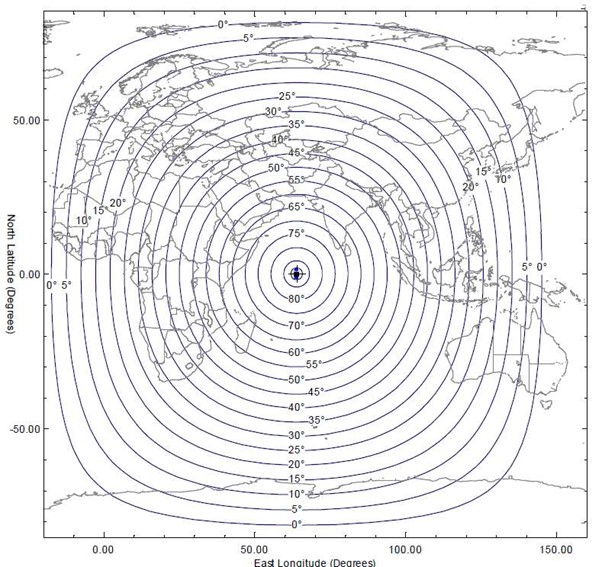
Figure 1.9M - Inmarsat I-3 IOR Satellite Coverage Map
Source:
Safety Investigation Report MH370/01/2018
MH370 departed KLIA at 1642 UTC [0042 MYT, 08 March 2014]. At 1707 UTC, the SATCOM system was used to send a standard ACARS report, normally sent every 30 minutes. The message also indicated the remaining fuel on-board.
The ACARS reports expected at 1737 UTC and 1807 UTC were not received. The next SATCOM communication was a log-on request from the aircraft at 1825 UTC. From that point until 0011 UTC, SATCOM transmissions indicate that the link was available, although not used for any voice, ACARS or other data services apart from two unanswered ground-to-air telephone calls. At 0019 UTC, the AES initiated another log-on request. The log-on acknowledge was the last transmission from the SATCOM.
The SATCOM link was available for most of the flight, excluding a period of between 22 and 78 minutes leading up to 1825 UTC, 07 March and a period of less than 8 minutes leading up to 0019 UTC, 08 March 2014. The absence of any aircraft-initiated handshakes, and on-going success of ground-initiated handshakes, indicates that power to the SATCOM was maintained other than the two periods stated above.
Data from the last seven ‘handshakes’ were used to help establish the most probable location of the aircraft. Initially only the first six of these ‘handshakes’ were considered to be complete. The seventh and last ‘handshake’ that was automatically initiated by the aircraft, was originally assessed as a partial ‘handshake’. Subsequent analysis confirmed the 7th handshake could be used to help determine the most probable flight path. Two unanswered ground-to-air telephone calls had the effect of resetting the activity log and hence increased the period between the ground initiated ‘handshakes’. The significant times used to identify the most probable final location of the aircraft are tabulated in Table 1.9B below. Details of the event’s SATCOM ground station logs are provided in Section 1.9.5 para. 3) and 4) (below).
| SATCOM TRANSMISSIONS | TIME | ||
|---|---|---|---|
| UTC | MYT* | ||
| 1. | Aircraft departed KLIA | 1642 | 0042 |
| 2. | Last ACARS transmission | 1707 | 0107 |
| 3. | 1st handshake - log-on initiated by the aircraft | 1825 | 0225 |
| 4. | Unanswered ground-to-air telephone call | 1839 | 0239 |
| 5. | 2nd handshake initiated by ground station | 1941 | 0341 |
| 6. | 3rd handshake initiated by ground station | 2041 | 0441 |
| 7. | 4th handshake initiated by ground station | 2141 | 0541 |
| 8. | 5th handshake initiated by ground station | 2241 | 0641 |
| 9. | Unanswered ground-to-air telephone call | 2313 | 0713 |
| 10. | 6th handshake initiated by ground station | 0011* | 0811 |
| 11. | 7th handshake - log-on initiated by the aircraft | 0019* | 0819 |
| 12. | Aircraft did not respond to ‘handshake’ from Satellite Earth Ground Station | 0115* | 0915 |
| *08 March 2014 | |||
Table 1.9B - SATCOM ‘Handshakes’
3) Satellite Communications Ground Station Logs of the Event - Summary
The SATCOM utilised the Inmarsat Indian Ocean Region (IOR) I-3 satellite and the associated Perth Ground Earth Station (GES) throughout the flight. Inmarsat has confirmed that during the flight, no SATCOM signalling or traffic was routed via any other satellites (including MTSAT) to any other GESs (including MTSAT11 GESs).
________________________
11 MTSAT - A series of Japanese weather and aviation satellites and GESs. MTSAT-1R and MTSAT-2 satellites are interoperable with Inmarsat satellites.
The SATCOM provides the Satellite link for the following functions:
- Cockpit Voice - Call control via the Multi-function Control and Display Units (MCDUs) and audio via the cockpit Audio Management Unit (AMU) and associated headsets;
- Cockpit Packet Data (Data-2) - Interface via the ACARS Management Unit (MU); and
- Cabin Packet Data (Data-3) - Interface via the Panasonic System 3000i IFE equipment:
The GES logs contain the following key information for each transmission to and from the aircraft:
- Time tag, Satellite and GES (Note: the timestamp accuracy does vary between the different logs, but should always be <1 second, and usually to a few milliseconds);
- Channel Type, Channel Number (frequency), Received Carrier/Noise Density Ratio (C/No), channel Bit-Error-Rate (BER), Burst Frequency Offset (BFO) and Burst Timing Offset (BTO, or round trip delay); and
- All payload data (excluding voice frames) contained within the transmission - these are known as the Signal Unit contents.
The events are summarised below. All times are in UTC. In the summary below, times are truncated to the nearest minute (the format is Hours Minutes) and in Section 1.9.5 para. 4), times are truncated to the nearest second (the format is Hours Minutes:Seconds).
| No. | Summary of SATCOM Ground Station Logs |
|---|---|
| 1. | Prior to take-off, the SATCOM Logged On (normally) a number of times, the last time being at 1600, when it sent a valid Flight ID to the GES. The SATCOM link was available for both voice and data (known as Log-On Class 3). |
| 2. | After take-off, the IFE SMS email application sent a normal beginning-of-flight message at 1642 (containing the correct Airborne Earth Station [AES ID], Flight ID "MAS370", origin airport "WMKK", and destination airport "ZBAA"), indicating that the IFE was receiving the valid Flight ID, origin airport and destination airport from AIMS and the ICAO (AES) ID from the Satellite Data Unit (SDU) at this time. |
| 3. | The SATCOM link was available for most of the flight, excluding periods leading up to 1825 UTC, 07 March and 0019 UTC, 08 March 2014. |
| 4. | When the SATCOM link was re-established at the above times, no Flight ID was present |
| 5. | During each of the two in-flight Log Ons at 1825 UTC and 0019 UTC, the GES recorded abnormal frequency offsets for the burst transmission from the SATCOM. |
| 6. | There is no indication of the SATCOM link being manually Logged Off from the cockpit (via an MCDU). Such activity would have been captured in the GES logs, but it was not. |
| 7. | No Data - 2 ACARS traffic was observed after 1707 UTC 07 March 2014. |
| 8. | The IFE equipment set up two ground connections over SATCOM [for the SMS e-mail application and Built-In Test Equipment (BITE) application] after the SATCOM reestablished the link at 1825 UTC, 07 March 2014 (normal), but not after the SATCOM re-established the link at 0019 UTC, 08 March (abnormal). At no time during the flight was any user data sent over the link by means of the SMS/e-Mail application. |
| 9. | Two Ground-to-Air Telephone Calls were placed to the cockpit from MAS Operations Centre (MOC) at Airline Operational Communications (AOC) Q10 priority level at 1839 UTC and at 2313 UTC, 07 March 2014. Neither of the calls was answered. |
| 10. | The SATCOM responded normally to a series of roughly hourly Log-On Interrogations from the Perth GES, up to and including a Log-On Interrogation at 0011 UTC, 08 March 2014. The two unanswered ground to air calls at 1839 UTC and 2313 UTC reset the Perth GES inactivity timer and hence the LogOn Interrogations were not always hourly. |
| 11. | The last transmission received from the SATCOM occurred at 0019 UTC, 08 March 2014 and the SATCOM failed to respond to a series of three Log-On interrogations starting at 0115 UTC, 08 March 2014. |
4) Satellite Communications Ground Station Logs – Key Observations (in chronological order) (Table 1.9C [below])
| No. | Time (UTC) | Key Observations - Satellite Ground Station Logs |
|---|---|---|
| 1. | 1250:19 | Prior to take-off, the SATCOM initiates a normal Log-On as Class 1 (data only capable) via the Pacific Ocean Region (POR) I-3 satellite, using the Low Gain Antenna (LGA) subsystem, suggesting that ADIRU (Air Data Inertial Reference Unit) navigation data was not available to the SDU at this time. No flight ID is sent to the GES at this time. This is the first SATCOM activity recorded at the GES since 0802:27, suggesting that the SATCOM was not powered for a period of several hours, whilst the aircraft was on ground. This is quite normal. |
| 2. | 1555:57 | The SATCOM initiates a normal Log On Renewal as Class 1 (data only capable) via the POR I-3 satellite, using the LGA subsystem, this time with a valid Flight ID. |
| 3. | 1557:49 | The SATCOM initiates a normal Log-On as Class 3 (voice and data capable) via the POR I-3 satellite, using the High Gain Antenna (HGA) subsystem, with a valid Flight ID. This suggests that the ADIRU derived navigation data has become available at this time. |
| 4. | 1559:57 | The SATCOM initiates a Log-On handover as Class 3 (voice and data capable) to the IOR I-3 satellite, using the HGA subsystem, with a valid Flight ID. This suggests that the IOR is now considered to be the best available satellite. This is probably because either the line of sight to the IOR satellite is now clearer than that to the POR satellite, or the antenna gain in the direction of the IOR satellite has become higher than the antenna gain in the direction of the POR satellite. |
| 5. | 1642:04 | After take-off, the IFE SMS e-mail application sends a normal beginning-of-flight message. |
| 6. | 1707:48 | Last DATA-2 ACARS Message received at the GES. No further SATCOM Data-2 ACARS messages or acknowledgements were received at the GES for the remainder of the flight. This is abnormal and suggests that the on-board ACARS equipment either failed, or was disabled or powered down at some time between 1707:48 and around 1825:00. |
| 7. | 1803:41 | GES initiates a DATA-2 ACARS transmission (uplink), but receives no acknowledgement from the SATCOM.
|
| 8. | 1805:11 | GES initiates a DATA-2 ACARS transmission, but receives no acknowledgement from the SATCOM, indicating that there is still no SATCOM link at this time. |
| 9. | 1825:27 | SATCOM Log-On, initiated from the aircraft terminal.
|
| 10. | 1825:34 | SATCOM Log-On, successfully completed.
An OCXO provides a stable reference frequency for the SDU Radio Frequency (RF) transmit and receive circuits and also for SDU modem timing. Within the OCXO, a regulated oven keeps the crystal at an almost constant temperature if the ambient temperature in the crown area is between the ranges -55oC up to above +70oC. The oven also contains extra electrical regulation and isolation to ensure frequency accuracy and stability. The OCXO includes an oven ready flag, which triggers the Log-On initiation when the OCXO reaches its operating temperature. Extensive laboratory testing has revealed that during warm up, the OCXO frequency may vary non-linearly with time, but then settles with almost negligible variation. At power-on, the OCXO can exhibit either a rising or falling frequency gradient, before decaying over time to its normal steady state value. The testing has indicated that reasonable stability (within 2Hz/minute) is typically reached by around five minutes after an initial peak or overshoot. The testing has also shown that there can still be a significant frequency offset at the time that the oven ready flag initiates the Log-On process, so the Log-On request, Log-On Acknowledge and subsequent data bursts can all exhibit significant frequency offsets. |
| 11. | 1827:03 | The IFE sets up a Data-3 ground connection (X.25 circuit) over SATCOM for an SMS/e-mail application after the SATCOM link is re-established. |
| 12. | 1828:05 | The IFE sets up a Data-3 ground connection (X.25 circuit) over SATCOM for a BITE application after the SATCOM link is re established. |
| 13. | 1839:52 | Ground-to-air telephony call placed from a number with country code 60 (Malaysia)
|
| 14. | 1840:56 | The GES logs show that the unanswered Ground-to-Air telephony call was cleared by the calling party. |
| 15. | 1941:00 | Log-On Interrogation by the Perth GES, with a response from the SATCOM |
| 16. | 2041:02 | Log-On Interrogation by the Perth GES, with a response from the SATCOM |
| 17. | 2141:24 | Log-On Interrogation by the Perth GES, with a response from the SATCOM |
| 18. | 2241:19 | Log-On Interrogation by the Perth GES, with a response from the SATCOM |
| 19. | 2313:58 | Ground-to-air telephony call placed from a number with country code 60 (Malaysia)
|
| 20. | 2315:02 | The GES logs show that the unanswered Ground to Air telephony call was cleared by the calling party. |
| 21. | 0010:58 | Log-On Interrogation by the Perth GES, with a response from the SATCOM |
| 22. | 0019:29 | SATCOM Log-On, initiated from the aircraft terminal. This is the seventh ‘handshake’.
|
| 23. | 0019:37 | SATCOM Log-On, successfully completed
Note: This is the last transmission received from the aircraft terminal. |
| 24. | 0115:56 | Log-On Interrogation by the Perth GES, with no response from the SATCOM |
| 25. | 0116:06 | Log-On Interrogation by the Perth GES, with no response from the SATCOM. |
| 26. | 0116:15 | Log-On Interrogation by the Perth GES, with no response from the SATCOM. |
Table 1.9C - Chronology of Satellite Communications Ground Station Logs
5) Frequencies of Log-On Bursts
During each of the two in-flight Log-Ons that occurred at 1825 and 0019, the GES recorded abnormal frequency offsets for the SATCOM transmissions. This is in contrast with the ‘normal’ Log-On behaviour.
Table 1.9D (below) shows the frequencies of these Log-On bursts, as measured at the GES, plus differences from assumed reference frequencies (closest stable values in time, where the aircraft is assumed to be in level flight). The table also shows the very high delta frequencies between the respective Log-On Request and Log-On Acknowledge bursts.
| Log-On Time | 1825 | 0019 |
|---|---|---|
| BFO used as a reference (closest stable value, assume level flight) | 144Hz @ 1828:05 | 252Hz @ 0010:59 |
| Log-On Request BFO | 142Hz @ 1825:27 | 182Hz @ 0019:29 |
| Log-On Request C/No recorded at GES | 30.28 | 40.59 |
| Log-On Request Channel BER recorded at GES | 5 | 0 |
| Log-On Request Difference Frequency (from BFO reference) | -2Hz @ 1825:27 | -70Hz @ 0019:29 |
| Log-On Acknowledge BFO | 273Hz @ 1825:34 | -2Hz @ 0019:37 |
| Log-On Acknowledge C/No recorded at GES | 42.55 | 43.38 |
| Log-On Acknowledge Channel BER recorded at GES | 0 | 0 |
| Log-On Acknowledge Difference Frequency (from BFO reference) | +129Hz @ 1825:34 | -254Hz @ 0019:37 |
| Delta frequency between the Log-On Request and the Log-On Acknowledge bursts, plus time period | +131Hz over 7 seconds | -184Hz over 8 seconds |
Table 1.9D - Log-On Bursts